
Boolean Algebra and Logic Circuits: Worked Assignment Example
A worked Boolean algebra assignment from a Discrete Mathematics II module, at bachelors level. It gives the laws of Boolean algebra in one table, the method for building a truth table and for simplifying with a Karnaugh map, then five solved questions covering minimal forms, sum of products and reading logic circuit diagrams.
This is a worked Boolean algebra assignment from a bachelors module called Discrete Mathematics II for Computer Studies. It covers five questions: simplifying expressions into minimal forms, building truth tables, reading Karnaugh maps, finding the sum of products, and tracing a logic circuit back to its Boolean expression. Below the method sections you will find the full solutions, with each question transcribed as text above its image and the working shown step by step.
The three sections that follow are the method, written so you can work your own question rather than only read ours. The worked solutions start further down.
What Are the Laws of Boolean Algebra?
Ten pairs of rules cover almost every exam question. Each has an AND form and an OR form, and each lets you shorten an expression without changing its truth table. De Morgan’s laws are the pair markers test most, because they are the only way to get a negation out of a bracket.
| Law | AND form | OR form |
|---|---|---|
| Identity | A · 1 = A | A + 0 = A |
| Null | A · 0 = 0 | A + 1 = 1 |
| Idempotent | A · A = A | A + A = A |
| Complement | A · ~A = 0 | A + ~A = 1 |
| Double negation | ~(~A) = A | ~(~A) = A |
| Commutative | A · B = B · A | A + B = B + A |
| Associative | (A · B) · C = A · (B · C) | (A + B) + C = A + (B + C) |
| Distributive | A · (B + C) = A · B + A · C | A + B · C = (A + B) · (A + C) |
| Absorption | A · (A + B) = A | A + A · B = A |
| De Morgan | ~(A · B) = ~A + ~B | ~(A + B) = ~A · ~B |
In this assignment · and ∧ both mean AND, + and ∨ both mean OR, and ~ means NOT. Module notation varies, so use whichever your lecturer uses and say so once at the top of your answer.
To learn the table for an exam, cover the two right-hand columns and write them out from memory; our revision plan for university exams explains why that works better than re-reading.
How Do You Build a Truth Table for a Boolean Expression?
Count the variables first. With n variables the table has 2 to the power n rows: three variables give eight rows. Then list every input combination in binary counting order, add one column per intermediate term, and work outwards from the innermost bracket.
- Write the input columns and fill them in binary counting order, from all zeros to all ones. This stops you missing a row.
- Add a column for every negation and every bracket in the expression. Question 2 below does this, with separate ~A, ~B and AC columns.
- Evaluate innermost brackets first. Where there are no brackets, NOT binds tightest, then AND, then OR.
- The last column is the output. Check two rows by hand against the original expression before you trust the rest.
- Read the rows where the output is 1. Each becomes one AND term, and OR-ing those terms gives the sum of products, also called the disjunctive normal form. Kuphaldt (section 7.9) sets out the same conversion.
How Do You Simplify a Boolean Expression with a Karnaugh Map?
A Karnaugh map (Karnaugh, 1953) is the same information as a truth table, rearranged so that terms which can be combined sit next to each other. Label the grid in Gray code, copy in the 1s, group them, then keep only the variables that stay constant inside each group.
Simplifying a Boolean expression with a Karnaugh map, in six steps
- Label the grid in Gray code Draw a grid with 2 to the power n cells and label rows and columns 00, 01, 11, 10, so only one variable changes between neighbours.
- Copy in the 1s Copy the 1s from your truth table into the matching cells.
- Group the 1s in rectangles of 1, 2, 4 or 8 Groups may overlap, and they may wrap around the left, right, top and bottom edges.
- Make each group as large as you can Use as few groups as you can. A larger group means a shorter term.
- Keep the variables that stay the same For each group, keep the variables that are the same in every cell and drop the ones that change.
- OR the group terms together The result is the minimal sum of products.
The commonest lost mark is forgetting that the map wraps: the four corner cells of a four-variable map are neighbours and form a valid group of four. Kuphaldt (sections 8.6 and 8.7) draws both cases, rolling the map into a cylinder for the edges and folding it for the corners.
Need the service pages rather than the method? See computer science assignment help and maths and science assignment help, or browse computer science samples and maths and science samples.
Worked Boolean Algebra Questions: Discrete Mathematics II
Assignment Question: Simplify the given Boolean expressions into minimal forms using truth tables and logic gates. Evaluate the corresponding logic circuits for accuracy and efficiency.
Discrete Mathematics II for Computer Studies
Resources: Laws of Boolean Algebra
The assignment came with a resource sheet listing the laws of Boolean algebra: the same ten pairs as the table at the top of this page. Mano and Ciletti (2018, chapter 2) state them with proofs. Solutions 4 and 5 name the law at the step where it is used.
Question 1
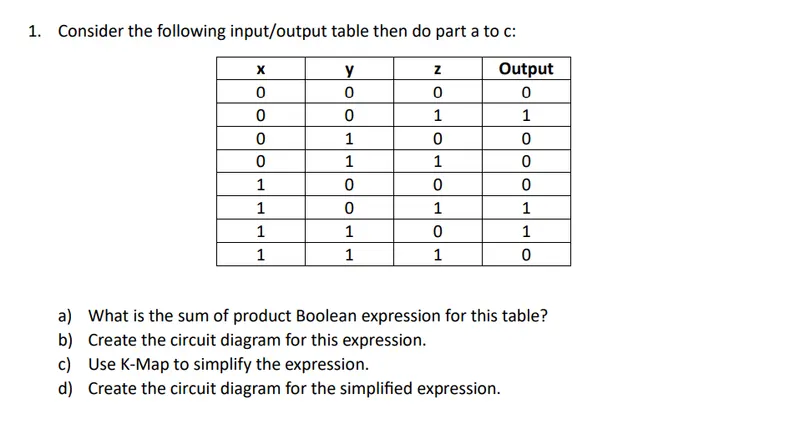
Consider the following input/output table, then do parts a to d.
| x | y | z | Output |
|---|---|---|---|
| 0 | 0 | 0 | 0 |
| 0 | 0 | 1 | 1 |
| 0 | 1 | 0 | 0 |
| 0 | 1 | 1 | 0 |
| 1 | 0 | 0 | 0 |
| 1 | 0 | 1 | 1 |
| 1 | 1 | 0 | 1 |
| 1 | 1 | 1 | 0 |
- What is the sum of products Boolean expression for this table?
- Create the circuit diagram for this expression.
- Use a Karnaugh map to simplify the expression.
- Create the circuit diagram for the simplified expression.
Solution 1
a)
The sum of products keeps only the rows where the output is 1. Three of the eight rows qualify:
| x | y | z | Output |
|---|---|---|---|
| 0 | 0 | 1 | 1 |
| 1 | 0 | 1 | 1 |
| 1 | 1 | 0 | 1 |
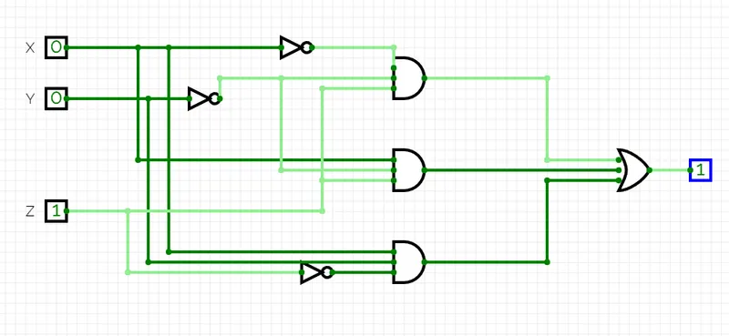
Output = (~x ∧ ~y ∧ z) ∨ (x ∧ ~y ∧ z) ∨ (x ∧ y ∧ ~z)
b)
c)
| ~z | z | |
|---|---|---|
| ~x~y | 0 | 1 |
| ~xy | 0 | 0 |
| xy | 1 | 0 |
| x~y | 0 | 1 |
The rows are labelled in Gray code order, ~x~y (00), ~xy (01), xy (11), x~y (10), so only one variable changes between neighbouring rows and the first and last rows are neighbours through the wrap-around. Two groups cover the three 1s. The cells ~x~y·z and x~y·z form a pair in which x changes and y and z stay the same, giving ~yz. The remaining 1 at xy·~z has no neighbour and stays as the full term xy~z.
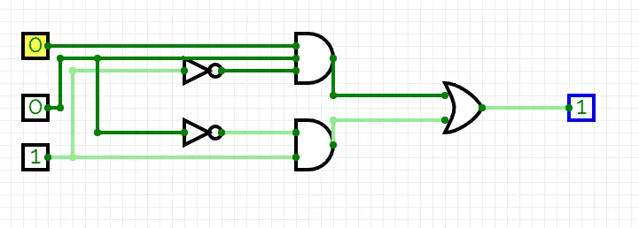
Simplified Expression: xy~z + ~yz
d)
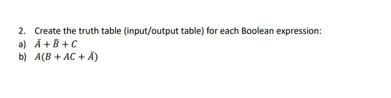
Question 2
Create the truth table (input/output table) for each Boolean expression:
- ~A + ~B + C
- A(B + AC + ~A)
Solution 2
a)
| A | B | C | ~A | ~B | ~A + ~B + C |
|---|---|---|---|---|---|
| 0 | 0 | 0 | 1 | 1 | 1 |
| 0 | 0 | 1 | 1 | 1 | 1 |
| 0 | 1 | 0 | 1 | 0 | 1 |
| 0 | 1 | 1 | 1 | 0 | 1 |
| 1 | 0 | 0 | 0 | 1 | 1 |
| 1 | 0 | 1 | 0 | 1 | 1 |
| 1 | 1 | 0 | 0 | 0 | 0 |
| 1 | 1 | 1 | 0 | 0 | 1 |
b)
| A | B | C | AC | ~A | B + AC + ~A | A(B + AC + ~A) |
|---|---|---|---|---|---|---|
| 0 | 0 | 0 | 0 | 1 | 1 | 0 |
| 0 | 0 | 1 | 0 | 1 | 1 | 0 |
| 0 | 1 | 0 | 0 | 1 | 1 | 0 |
| 0 | 1 | 1 | 0 | 1 | 1 | 0 |
| 1 | 0 | 0 | 0 | 0 | 0 | 0 |
| 1 | 0 | 1 | 1 | 0 | 1 | 1 |
| 1 | 1 | 0 | 0 | 0 | 1 | 1 |
| 1 | 1 | 1 | 1 | 0 | 1 | 1 |
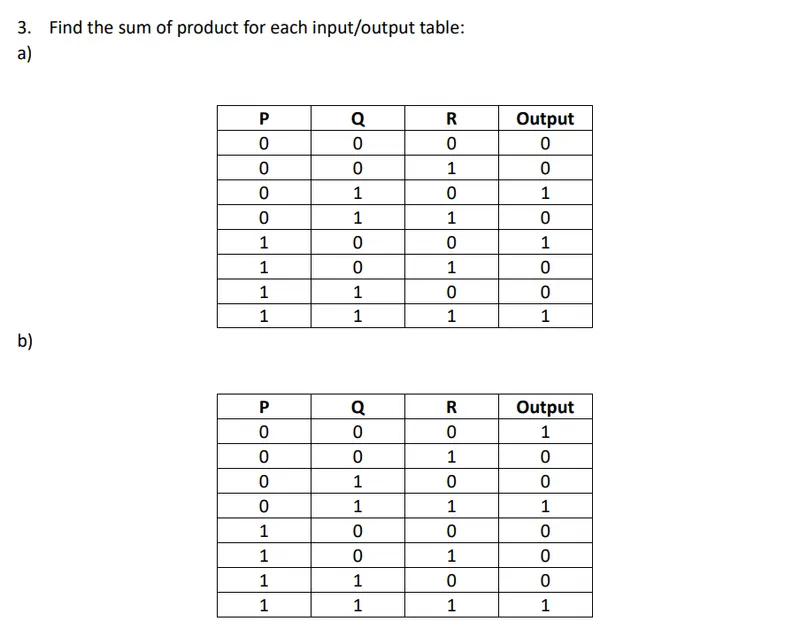
Question 3
Find the sum of products for each input/output table. The two tables describe different functions, so the two answers differ.
| P | Q | R | Output |
|---|---|---|---|
| 0 | 0 | 0 | 0 |
| 0 | 0 | 1 | 0 |
| 0 | 1 | 0 | 1 |
| 0 | 1 | 1 | 0 |
| 1 | 0 | 0 | 1 |
| 1 | 0 | 1 | 0 |
| 1 | 1 | 0 | 0 |
| 1 | 1 | 1 | 1 |
| P | Q | R | Output |
|---|---|---|---|
| 0 | 0 | 0 | 1 |
| 0 | 0 | 1 | 0 |
| 0 | 1 | 0 | 0 |
| 0 | 1 | 1 | 1 |
| 1 | 0 | 0 | 0 |
| 1 | 0 | 1 | 0 |
| 1 | 1 | 0 | 0 |
| 1 | 1 | 1 | 1 |
Solution 3
a)

The rows where the output is 1 are P=0, Q=1, R=0; P=1, Q=0, R=0; and P=1, Q=1, R=1. Each becomes one AND term.
Output = (~P∧Q∧~R) ∨ (P∧~Q∧~R) ∨ (P∧Q∧R)
No two of those three terms differ in exactly one variable, so there is nothing to combine and this is already the minimal sum of products.
b)
| P | Q | R | Output |
|---|---|---|---|
| 0 | 0 | 0 | 1 |
| 0 | 1 | 1 | 1 |
| 1 | 1 | 1 | 1 |
Output = (~P∧~Q∧~R) ∨ (~P∧Q∧R) ∨ (P∧Q∧R)
Here two terms can be combined: ~P·Q·R and P·Q·R differ only in P, so they reduce to Q·R. The minimal form is therefore ~P~Q~R + QR, which is shorter than the answer to part a because part b describes a different function.
Question 4
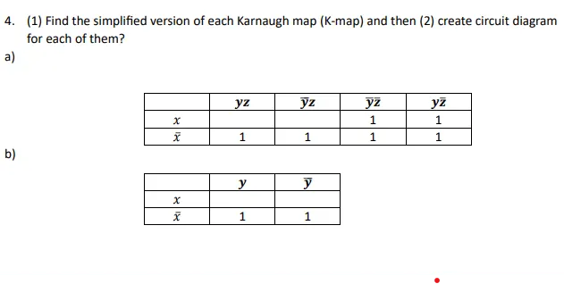
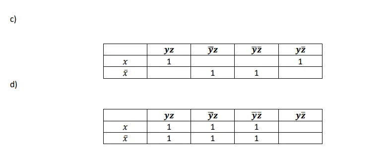
For each Karnaugh map below, (1) find the simplified expression and (2) create a circuit diagram for it. The columns are labelled in Gray code order, so the first and last columns are neighbours. An empty cell is a 0.
| yz | ~yz | ~y~z | y~z | |
|---|---|---|---|---|
| x | 1 | 1 | ||
| ~x | 1 | 1 | 1 | 1 |
| y | ~y | |
|---|---|---|
| x | ||
| ~x | 1 | 1 |
| yz | ~yz | ~y~z | y~z | |
|---|---|---|---|---|
| x | 1 | 1 | ||
| ~x | 1 | 1 |
| yz | ~yz | ~y~z | y~z | |
|---|---|---|---|---|
| x | 1 | 1 | 1 | |
| ~x | 1 | 1 | 1 |
Solution 4
a)
The whole ~x row is 1, which is a group of four giving ~x. The two ~z columns, ~y~z and y~z, are 1 in both rows, which is a second group of four giving ~z. Every 1 is now covered by one of the two groups.
Output = ~x ∨ ~z
The check is the pair of cells that are 0: x·yz and x·~yz, which are exactly the cells where x and z are both 1. The function is therefore the complement of x·z, and by De Morgan that is ~x + ~z.
Circuit: x and z each pass through a NOT gate, and the two outputs feed one two-input OR gate.
b)
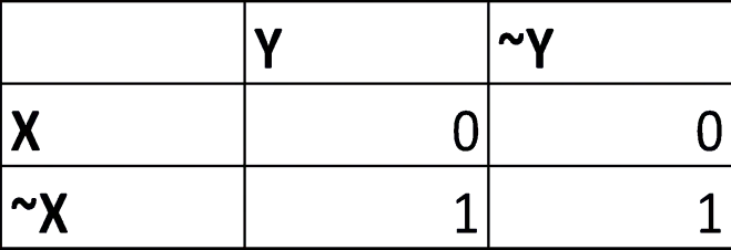
Output = ~x
Circuit: a single NOT gate on x. The output does not depend on y, so y is left unconnected.
c)

The 1s sit in the x row under yz and y~z, which pair into x·y, and in the ~x row under ~yz and ~y~z, which pair into ~x·~y. The two pairs are not adjacent to each other, so neither group can be grown.
Output = (x∧y) ∨ (~x∧~y)
z drops out of both terms because it changes inside each group. The result is the exclusive-NOR of x and y: the output is 1 whenever x and y agree.
Circuit: one AND gate takes x and y, and a second takes ~x and ~y from two NOT gates; both outputs feed one OR gate. A single XNOR gate on x and y does the same job.
d)

Six of the eight cells are 1. The three columns yz, ~yz and ~y~z are 1 in both rows, so x drops out, and the only column that is 0 is y~z. Taking the 1s: the yz and ~yz columns give z, and the ~yz and ~y~z columns give ~y.
Output = ~y ∨ z
Read the other way round, the output is 0 only when y is 1 and z is 0, so the function is the complement of y·~z, which by De Morgan is ~y + z.
Circuit: y passes through a NOT gate, and ~y and z feed one two-input OR gate.
Question 5
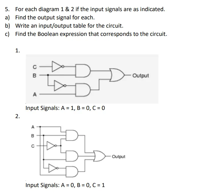
For each of diagrams 1 and 2, with the input signals as indicated:
- Find the output signal for each.
- Write an input/output table for the circuit.
- Find the Boolean expression that corresponds to the circuit.
Diagram 1. C passes through a NOT gate. The top AND gate takes B and ~C. B also branches to a second NOT gate, and the bottom AND gate takes that ~B together with A. The two AND outputs feed one OR gate. Input signals: A = 1, B = 0, C = 0.
Diagram 2. C passes through a NOT gate. The top gate is a three-input AND taking A, B and ~C. The middle AND gate takes B and the same ~C. B also branches to a second NOT gate, and the bottom AND gate takes that ~B together with A. All three AND outputs feed one OR gate. Input signals: A = 0, B = 0, C = 1.
Solution 5
This solution works through both circuits: the output for the given input signals, the full input/output table, and the Boolean expression the circuit implements. The two circuits are not the same drawing, and part of the answer is explaining what the difference between them does.
1a) Output
Inputs: A = 1, B = 0, C = 0
Output: 1
Explanation:
C is 0, so the NOT gate on C puts a 1 on the top input of the topmost AND gate, and B puts a 0 on its bottom input. The topmost AND gate therefore gives AND(1, 0) = 0. The bottom AND gate has inputs ~B (1) and A (1), so its output is 1. Therefore, the OR gate inputs are 0 and 1. OR of 0 and 1 is 1. Thus our output is 1.
1b) Input/Output Table
| A | B | C | Output |
|---|---|---|---|
| 0 | 0 | 0 | 0 |
| 0 | 0 | 1 | 0 |
| 0 | 1 | 0 | 1 |
| 0 | 1 | 1 | 0 |
| 1 | 0 | 0 | 1 |
| 1 | 0 | 1 | 1 |
| 1 | 1 | 0 | 1 |
| 1 | 1 | 1 | 0 |
1c) Boolean Expression
Read straight off the gates, circuit 1 is (B ∧ ~C) ∨ (A ∧ ~B). Expanding that over the four rows where the output is 1 gives the disjunctive normal form, and grouping the adjacent rows gives it back in minimal form.
Disjunctive normal form = ~AB~C + A~B~C + A~BC + AB~C
Minimal form = B~C + A~B
2a) Output
Inputs: A = 0, B = 0, C = 1
Output: 0
Explanation:
The topmost gate is a three-input AND taking A, B and ~C. A is 0, so its output is 0. The middle AND gate takes B and ~C. B is 0, so its output is 0 as well. The bottom AND gate takes A and ~B: here ~B is 1, but A is 0, so that gate also gives 0. The OR gate therefore sees 0, 0 and 0, and the output is 0.
2b) Input/Output Table
| A | B | C | Output |
|---|---|---|---|
| 0 | 0 | 0 | 0 |
| 0 | 0 | 1 | 0 |
| 0 | 1 | 0 | 1 |
| 0 | 1 | 1 | 0 |
| 1 | 0 | 0 | 1 |
| 1 | 0 | 1 | 1 |
| 1 | 1 | 0 | 1 |
| 1 | 1 | 1 | 0 |
2c) Boolean Expression
Circuit 2 reads off the gates as (A ∧ B ∧ ~C) ∨ (B ∧ ~C) ∨ (A ∧ ~B), which is one term longer than circuit 1. The extra term is absorbed: A·B·~C is a special case of B·~C, and by the absorption law B·~C + A·B·~C = B·~C. What is left is the same function as circuit 1, which is why the table in 2b is identical to the one in 1b.
Disjunctive normal form = ~AB~C + A~B~C + A~BC + AB~C
Minimal form = B~C + A~B
That is the point of setting the two diagrams together. Circuit 2 is accurate, because it computes the right function, but it is not efficient: its three-input AND gate costs hardware and adds a gate delay while changing nothing about the output. On the efficiency criterion in the assignment brief, circuit 1 is the better implementation of the two.
Need a similar set of Boolean algebra or discrete maths solutions worked through? Message us on WhatsApp with the question sheet and your deadline.
Sources
- Mano, M. M. and Ciletti, M. D. (2018). Digital Design: With an Introduction to the Verilog HDL, VHDL, and SystemVerilog, 6th edition. Pearson. Chapter 2 covers the laws of Boolean algebra and canonical forms; chapter 3 covers Karnaugh maps and gate-level minimisation. Publisher page
- Karnaugh, M. (1953). The map method for synthesis of combinational logic circuits. Transactions of the American Institute of Electrical Engineers, Part I: Communication and Electronics, 72(5), 593–599. The paper the Karnaugh map comes from, including the Gray-code labelling used above. https://doi.org/10.1109/TCE.1953.6371932
- Kuphaldt, T. R. Electric Circuits IV: Digital Circuitry, chapter 7 (Boolean algebra; section 7.9 converts a truth table into a sum of products) and chapter 8 (Karnaugh mapping; sections 8.6 and 8.7 cover grouping, wrap-around and four-variable maps). Open textbook, LibreTexts. Boolean algebra, Karnaugh mapping
Related samples: computer science dissertation sample, how data mining improves e-commerce personalisation, report on mobile cloud computing, probability and statistics assignment help, shear force and bending moment diagram worked example, and final project ideas for computer science students.
Frequently Asked Questions
What are the laws of Boolean algebra?
Ten pairs cover almost every exam question: identity, null, idempotent, complement, double negation, commutative, associative, distributive, absorption and De Morgan. Each has an AND form and an OR form. De Morgan's laws are the ones markers test most, because they turn a negated bracket into a usable expression.
How do you build a truth table for a Boolean expression?
Count the variables. With n variables the table has 2 to the power n rows. List the input combinations in binary counting order, add one column for each intermediate term, evaluate innermost brackets first and AND before OR, then read the output column. The rows where the output is 1 give the sum of products.
How do you simplify a Boolean expression with a Karnaugh map?
Copy the 1s from the truth table into a grid labelled in Gray code, so only one variable changes between neighbouring cells. Group the 1s into rectangles of 1, 2, 4 or 8, as large and as few as possible. Keep the variables that stay constant in each group, drop the ones that change, then OR the groups.
What is the difference between a truth table and a Karnaugh map?
A truth table tells you what an expression does; a Karnaugh map tells you how to make it shorter. The table lists every input combination and its output. The map rearranges the same information so that terms which can be combined sit next to each other, which makes the minimal form visible.
What level is this Boolean algebra assignment?
Bachelors level, from a module called Discrete Mathematics II for Computer Studies. It assumes you know the gate symbols and truth tables and are being tested on minimal forms, sum of products, Karnaugh maps and reading a circuit diagram back into an expression.