
Shear Force and Bending Moment Diagrams: A Worked Steel Beam Assignment Example
A worked shear force and bending moment diagram example on a 6.0 m simply supported beam with a UDL and point load. It finds reactions of 54.0 and 42.0 kN, a maximum moment of 73.5 kN m at 2.5 m, then checks a 254 x 146 x 31 UB: 68 percent in bending, 8.7 mm deflection against 16.7 mm allowed.
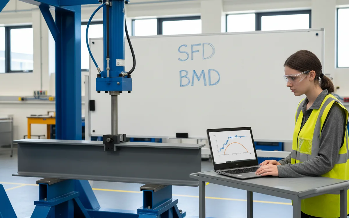
This is a worked shear force and bending moment diagram example of the kind set in a first structures or mechanics module: one simply supported steel floor beam, 6.0 m long, carrying a uniformly distributed load and a point load. Every number is computed on the page and every line carries its unit.
It is a worked example for study, not a design to build: the checks show how the clauses are applied, not advice about any real structure. Our engineering assignment help covers structures, mechanics and the engineering maths behind them, and more worked samples sit in computer science assignment samples, which includes our engineering samples, and in maths and science samples.
What Is the Beam Problem in This Worked Example?
A 6.0 m simply supported steel beam carries a UDL and a point load at 1.5 m from A, factored to 12.0 kN/m and 24.0 kN. The reactions are 54.0 and 42.0 kN, the maximum moment is 73.5 kN m at 2.5 m, and a 254 x 146 x 31 UB in S275 passes every check in this exercise.
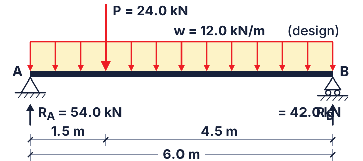
The question as set (characteristic loads)
Beam: simply supported, span L = 6.0 m, pin at A (x = 0), roller at B (x = 6.0 m)
UDL over the full span: permanent gk = 5.0 kN/m, variable qk = 3.5 kN/m
Point load from a secondary beam, 1.5 m from A: permanent Gk = 10 kN, variable Qk = 7 kN
Trial section: 254 x 146 x 31 UB, grade S275
The beam's own weight, 31.1 kg/m or about 0.31 kN/m, is inside gk. The sheet asks for:
- ULS design loads, BS EN 1990 expression 6.10;
- support reactions;
- shear force and bending moment diagrams with key values;
- maximum bending moment and its position;
- bending and shear checks, BS EN 1993-1-1;
- a deflection check for a brittle finish.
One assumption comes before any calculation: the floor restrains the top flange laterally along its length, which is why lateral-torsional buckling is not checked below. A beam without that restraint also needs clause 6.3.2 of BS EN 1993-1-1, and an answer that never states the assumption leaves the examiner guessing whether the writer knew it mattered.
How Do You Work Out the Design Loads and the Support Reactions?
Factor the loads, then take moments about one support. Expression 6.10 of BS EN 1990 (1.35 on permanent, 1.5 on variable actions) gives a design UDL of 12.0 kN/m and a design point load of 24.0 kN. Moments about A give RB = 42.0 kN; vertical equilibrium gives RA = 54.0 kN, and together they carry the 96.0 kN applied.
The factors are the UK National Annex values in Table NA.A1.2(B) of BS EN 1990, as printed on SteelConstruction.info's design codes page, which also lists the alternative pair 6.10a and 6.10b; the sheet names 6.10, and your answer should say which expression it used.
Design loads (ULS)
wEd = 1.35 × 5.0 + 1.5 × 3.5 = 6.75 + 5.25 = 12.0 kN/m
PEd = 1.35 × 10 + 1.5 × 7 = 13.5 + 10.5 = 24.0 kN
Total distributed load = 12.0 × 6.0 = 72.0 kN, acting at midspan, 3.0 m from A
Reactions. The free body has RA upward at x = 0, RB upward at x = 6.0 m, 72.0 kN downward at 3.0 m and 24.0 kN downward at 1.5 m. Taking moments about A, clockwise positive:
RB × 6.0 = 72.0 × 3.0 + 24.0 × 1.5 = 216.0 + 36.0 = 252.0 kN m
RB = 252.0 / 6.0 = 42.0 kN
Vertical equilibrium: RA = 72.0 + 24.0 − 42.0 = 54.0 kN
Write the check as a sentence, not bare arithmetic: RA + RB = 96.0 kN, the total applied load, and moments about B give RA × 6.0 = 72.0 × 3.0 + 24.0 × 4.5 = 324.0 kN m, so RA = 54.0 kN again. A wrong reaction is the costliest error on a beam question, because it is carried into every shear value, every moment value and both resistance checks.
How Do You Draw the Shear Force Diagram?
Start at A with V = RA = 54.0 kN, fall at 12.0 kN per metre under the UDL, drop by 24.0 kN at the point load and arrive at −42.0 kN (minus RB) at B. The shear crosses zero at x = 2.5 m. Join the values with straight lines, because a uniform load gives a linear shear.
Shear force diagram for the 6.0 m beam, V(x) in kN
Chart data
| Point (m) | Shear force V |
|---|---|
| 0 | 54 kN |
| 0.5 | 48 kN |
| 1 | 42 kN |
| 1.5 (just left) | 36 kN |
| 1.5 (just right) | 12 kN |
| 2 | 6 kN |
| 2.5 | 0 kN |
| 3 | -6 kN |
| 3.5 | -12 kN |
| 4 | -18 kN |
| 4.5 | -24 kN |
| 5 | -30 kN |
| 5.5 | -36 kN |
| 6 | -42 kN |
The sign convention comes from Udoeyo's Structural Analysis, section 1.4: "a shear force that tends to move the left of the section upward or the right side of the section downward will be regarded as positive", and a bending moment is positive when it causes sagging. Under this convention dV/dx = −w and dM/dx = V, and every expression below obeys it.
Cut the beam at a distance x from A and sum the vertical forces to the left of the cut. There are two regions, because the point load changes the expression at 1.5 m.
Region 1, 0 ≤ x < 1.5 m
V(x) = RA − wEd x = 54.0 − 12.0x
V(0) = 54.0 kN
V just left of the load, x = 1.5 m: 54.0 − 18.0 = 36.0 kN
Region 2, 1.5 m < x ≤ 6.0 m
V(x) = 54.0 − 12.0x − 24.0 = 30.0 − 12.0x
V just right of the load, x = 1.5 m: 30.0 − 18.0 = 12.0 kN
V(6.0) = 30.0 − 72.0 = −42.0 kN, which is −RB, so the diagram closes
Zero shear: 30.0 − 12.0x = 0, so x = 2.5 m from A
The drop at 1.5 m is exactly the point load, 36.0 − 12.0 = 24.0 kN, which is the second check on this section: every vertical step in a shear diagram must equal a point load or a reaction, and the total of the steps and slopes must return the diagram to zero at the far end.
How Do You Draw the Bending Moment Diagram?
Take moments of everything to the left of the cut, sagging positive. Left of the point load, M = 54.0x − 6.0x², which gives 67.5 kN m at the load. Beyond it the load's own moment is subtracted, the curve peaks at 73.5 kN m at 2.5 m where the shear is zero, and returns to zero at B.
Bending moment diagram for the 6.0 m beam, M(x) in kN m
Chart data
| Point (m) | Bending moment M |
|---|---|
| 0 | 0 kN m |
| 0.5 | 25.5 kN m |
| 1 | 48 kN m |
| 1.5 | 67.5 kN m |
| 2 | 72 kN m |
| 2.5 | 73.5 kN m |
| 3 | 72 kN m |
| 3.5 | 67.5 kN m |
| 4 | 60 kN m |
| 4.5 | 49.5 kN m |
| 5 | 36 kN m |
| 5.5 | 19.5 kN m |
| 6 | 0 kN m |
Region 1, 0 ≤ x ≤ 1.5 m
M(x) = RA x − wEd x² / 2 = 54.0x − 6.0x²
M(0) = 0
M(1.5) = 81.0 − 13.5 = 67.5 kN m
Region 2, 1.5 m ≤ x ≤ 6.0 m
M(x) = 54.0x − 6.0x² − 24.0(x − 1.5)
M(2.5) = 135.0 − 37.5 − 24.0 = 73.5 kN m
M(3.0) = 162.0 − 54.0 − 36.0 = 72.0 kN m
M(6.0) = 324.0 − 216.0 − 108.0 = 0, so the diagram closes at B
Working from B gives the same peak: with 3.5 m of beam to the right of 2.5 m, M(2.5) = RB × 3.5 − 12.0 × 3.5² / 2 = 147.0 − 73.5 = 73.5 kN m. The area rule in Baker and Haynes, Engineering Statics, section 8.5 ("the change in the moment value between two points is the area under the shear curve between those points") gives a third route: the trapezium under the shear from 0 to 1.5 m, (54.0 + 36.0) / 2 × 1.5 = 67.5 kN m, is M(1.5), and the triangle to 2.5 m adds 12.0 × 1.0 / 2 = 6.0 kN m, so M(2.5) = 73.5 kN m.
The shape follows from the same rule. Where the shear is a sloping line the moment is a parabola; where the shear steps down by 24.0 kN the slope of the moment diagram changes by 24.0 kN m per metre, which is the kink at 1.5 m; and where the shear passes through zero the moment is flat, which is the peak. A moment diagram that fails to close to zero at a roller has an arithmetic error somewhere upstream.
The chart draws sagging above the axis, as Udoeyo does ("positive bending moments are drawn above the x-centroidal axis"). Some modules draw on the tension side instead, which puts sagging below; follow your module and label the diagram.
Where Is the Maximum Bending Moment, and Why Is It Where the Shear Force Is Zero?
At 2.5 m from A, not at midspan, with Mmax = 73.5 kN m. Because dM/dx = V, the moment is stationary wherever the shear passes through zero, and on a sagging beam that point is the maximum. Solve V(x) = 30.0 − 12.0x = 0 rather than assuming the middle: midspan gives 72.0 kN m, 2 percent low.
Udoeyo's section 1.4 states the rule directly: "maximum bending moment occurs where the shearing force equals zero". The point load pulls the crossing from midspan towards A by its moment about A over the total UDL, PEd a / (wEd L) = 24.0 × 1.5 / (12.0 × 6.0) = 0.5 m, from 3.0 m to 2.5 m, where a is its distance from A. A heavier load, or the same load further from A, pulls it further, until the crossing reaches the load (at a = 2.25 m for these loads). Beyond that the shear jumps across zero at the load without touching it, and the maximum sits under the load: read it from the moment expression rather than solving V = 0.
Does a 254 x 146 x 31 UB in S275 Pass the Bending and Shear Checks?
It passes both in this exercise. The section is Class 1, so its plastic modulus of 393 cm³ applies and Mc,Rd = 108.1 kN m against MEd = 73.5 kN m, a utilisation of 0.68. The plastic shear resistance is 260.3 kN against VEd = 54.0 kN, below half of Vpl,Rd, so the moment resistance needs no reduction for shear.
Section check results, 254 x 146 x 31 UB in S275
- Design moment M_Ed
- 73.5 kN m At 2.5 m from A; 72.0 kN m at midspan.
- Moment resistance M_c,Rd
- 108.1 kN m Class 1, so W_pl,y = 393 cm³; W_el,y would give 96.5 kN m.
- Bending utilisation
- 68% M_Ed / M_c,Rd = 0.68.
- Shear resistance V_pl,Rd
- 260.3 kN A_v = 1,639 mm²; design shear V_Ed = 54.0 kN at support A.
- Shear utilisation
- 21% V_Ed / V_pl,Rd = 0.21.
- Half of V_pl,Rd
- 130.1 kN V_Ed is below it, so M_c,Rd is not reduced for shear (clause 6.2.8).
Section properties, from British Steel's universal beams datasheet
Mass 31.1 kg/m; depth h = 251.4 mm; width b = 146.1 mm
Web tw = 6.0 mm; flange tf = 8.6 mm; root radius r = 7.6 mm
Depth between fillets d = 219.0 mm; area A = 39.7 cm²
Second moment of area Iy = 4,413 cm⁴
Elastic modulus Wel,y = 351 cm³; plastic modulus Wpl,y = 393 cm³
Material, from SteelConstruction.info's steel material properties and member design pages
S275 with tf = 8.6 mm ≤ 16 mm, so fy = 275 N/mm² (BS EN 10025-2); E = 210,000 N/mm²; γM0 = 1.00 (UK National Annex)
Classification, Table 5.2 of BS EN 1993-1-1 (Class 1 limits: 9ε for an outstand flange in compression, 72ε for a web in bending)
ε = √(235 / fy) = √(235 / 275) = 0.924
Flange outstand c = (b − tw − 2r) / 2 = (146.1 − 6.0 − 15.2) / 2 = 62.45 mm; c / tf = 62.45 / 8.6 = 7.26 ≤ 9ε = 8.32, so the flange is Class 1
Web c = d = 219.0 mm; c / tw = 219.0 / 6.0 = 36.5 ≤ 72ε = 66.6, so the web is Class 1 in bending
The section is Class 1, and Wpl,y applies
The datasheet prints B/2T = 8.49, which is the whole half-flange over its thickness; Table 5.2 measures the outstand from the root fillet, so 7.26 is the figure compared with the limit. A section that came out Class 3 would use Wel,y instead, and here that would give 351 × 10³ mm³ × 275 N/mm² / 1.00 = 96.5 × 10⁶ N mm = 96.5 kN m, a utilisation of 0.76 rather than 0.68. The class decides the modulus; the modulus is not a free choice.
Bending resistance, clause 6.2.5
Wpl,y = 393 cm³ = 393 × 10³ mm³
Mc,Rd = Wpl,y fy / γM0 = 393 × 10³ mm³ × 275 N/mm² / 1.00 = 108.1 × 10⁶ N mm
10⁶ N mm = 1 kN m, so Mc,Rd = 108.1 kN m
MEd / Mc,Rd = 73.5 / 108.1 = 0.68, which is less than 1.0
Shear resistance, clause 6.2.6
Shear area for a rolled I-section loaded parallel to the web, clause 6.2.6(3)(a), with A = 39.7 cm² = 3,970 mm²:
Av = A − 2 b tf + (tw + 2r) tf = 3,970 − 2 × 146.1 × 8.6 + (6.0 + 15.2) × 8.6 = 3,970 − 2,512.9 + 182.3 = 1,639 mm²
The clause sets a minimum of η hw tw; with η = 1.0, the conservative value, and hw = 251.4 − 2 × 8.6 = 234.2 mm, that is 1.0 × 234.2 × 6.0 = 1,405 mm², so 1,639 mm² stands
Shear buckling: hw / tw = 234.2 / 6.0 = 39.0 ≤ 72ε / η = 66.6 (55.5 if η = 1.2), so clause 6.2.6(6) calls for no shear buckling check
Vpl,Rd = Av (fy / √3) / γM0 = 1,639 mm² × (275 / 1.732) N/mm² / 1.00 = 1,639 × 158.8 = 260,300 N = 260.3 kN
VEd = RA = 54.0 kN, the largest shear on the beam; VEd / Vpl,Rd = 0.21
0.5 Vpl,Rd = 130.1 kN, and 54.0 kN is below it
The Mc,Rd and Vpl,Rd expressions are as printed on the SteelConstruction.info member design page, with the clause 6.2.8 rule that shear below 0.5 Vpl,Rd may be neglected "except where shear buckling reduces the section resistance". The hw / tw line closes that exception, and at 2.5 m, where the moment peaks, the shear is zero. The same page says "beams with sufficient restraint to the compression flange are not susceptible to lateral-torsional buckling"; without the floor, the beam needs a clause 6.3.2 check, named here and not computed.
Does the Beam Pass the Deflection Check?
It does, in this exercise. Under unfactored variable actions alone, the 3.5 kN/m UDL deflects the beam 6.37 mm at midspan and the 7 kN point load adds 2.34 mm there: 8.7 mm in total against the span/360 limit of 16.7 mm under a brittle finish. The UK National Annex leaves the permanent actions out.
The limits are the suggested values in the UK National Annex to BS EN 1993-1-1, as tabled on SteelConstruction.info's design codes page: span/360 under plaster or another brittle finish, span/200 for other beams, length/180 for cantilevers, all under variable actions only; a client can agree others for a project. Deflection is a serviceability check, so no partial factors apply.
Values for the check
qk = 3.5 kN/m = 3.5 N/mm; Qk = 7 kN = 7,000 N; L = 6,000 mm
E = 210,000 N/mm²; Iy = 4,413 cm⁴ = 4.413 × 10⁷ mm⁴
E Iy = 210,000 × 4.413 × 10⁷ = 9.267 × 10¹² N mm²
The formulas below come from the American Wood Council's Design Aid 6. They are elastic results, valid for any material in consistent units, and follow from integrating EI d²y/dx² = M twice (Udoeyo, section 1.7).
UDL at midspan (Design Aid 6, Figure 1)
δ1 = 5 qk L⁴ / (384 E I) = 5 × 3.5 × 6,000⁴ / (384 × 9.267 × 10¹²) = 6.37 mm
Point load, 1.5 m from A (Design Aid 6, Figure 8)
Figure 8 gives the maximum for a > b, with x and a measured from the same support, so read this beam from B: a = 4,500 mm (B to the load), b = 1,500 mm (load to A), a + 2b = 7,500 mm
At midspan x = 3,000 mm, which is less than a: δ2 = Qk b x (L² − b² − x²) / (6 E I L) = 7,000 × 1,500 × 3,000 × (6,000² − 1,500² − 3,000²) / (6 × 9.267 × 10¹² × 6,000) = 2.34 mm
The load is off-centre, so its own maximum is not at midspan: δmax = Qk a b (a + 2b) √(3a(a + 2b)) / (27 E I L) = 7,000 × 4,500 × 1,500 × 7,500 × √(3 × 4,500 × 7,500) / (27 × 9.267 × 10¹² × 6,000) = 2.38 mm
It occurs at x = √(a(a + 2b) / 3) = √(4.5 × 7.5 / 3) = 3.35 m from B, which is 2.65 m from A; the midspan value is 1.6 percent below it
Total and limit
Superposition applies because the equations are linear: Roylance, section 4.3, "the response to a combination of loads is the sum of the responses that would be generated by each separate load acting alone"
At midspan: δ = 6.37 + 2.34 = 8.71 mm
The two maxima are 0.35 m apart, so their sum, 6.37 + 2.38 = 8.75 mm, is an upper bound on the deflection anywhere on the span
Limit for a brittle finish: L / 360 = 6,000 / 360 = 16.7 mm; 8.7 mm is 52 percent of it
For comparison, L / 200 = 30.0 mm for a beam with no brittle finish
A common mistake on this question is running the deflection with the ULS loads. Put 12.0 kN/m and 24.0 kN into the same midspan formulas and the answer is 29.9 mm, which fails the 16.7 mm limit and would send the student off to a heavier section for no reason.
What Loses Marks in a Shear Force and Bending Moment Assignment?
The mistakes we correct most often are unchecked reactions, mixed sign conventions and dropped units. A reaction that is 6 kN out puts every later number out; a shear formula from one textbook and a moment relation from another flip the sign of the diagram; a modulus left in cm³ against N/mm² gives a resistance a thousand times wrong.
What loses the mark and what earns it, step by step
| Point of comparison | What loses the mark | What earns it |
|---|---|---|
| Free-body diagram | What loses the mark No sketch; the reactions appear from nowhere | What earns it Beam, supports, factored loads and both reactions drawn and labelled before the first equation |
| Reactions | What loses the mark R_A found from one equation and never checked | What earns it R_A + R_B = 96.0 kN stated in a sentence, and R_A confirmed by moments about B |
| Sign convention | What loses the mark A shear formula from one textbook and a moment relation from another | What earns it One convention named once (left side up is positive shear, sagging is positive moment, dM/dx = V) and kept to the end |
| Units | What loses the mark kN mixed with N, cm³ with mm³, no unit on the final answer | What earns it Every line carries its unit; cm³ to mm³ and N mm to kN m converted where they happen |
| Section modulus | What loses the mark W_el used for a Class 1 section, or W_pl for a Class 3 | What earns it Class found from Table 5.2 first, then the modulus that class allows |
| Deflection | What loses the mark Factored ULS loads with the permanent actions included (29.9 mm here) | What earns it Unfactored variable actions only (8.7 mm here), against the limit the finish requires |
| Assumptions and labels | What loses the mark Restraint never stated; diagrams drawn with no values on them | What earns it Restraint assumption stated up front; every key value written on both diagrams |
The sign convention trap is set by good books. Roylance's Mechanics of Materials, section 4.1, counts shear as positive when it points upward on a face whose outward normal points along +x, the reverse of Udoeyo's left-side-up rule, so its relations read dV/dx = −q and dM/dx = −V; both books call sagging positive. Each set is correct inside its own convention. Take the shear expression from one and the moment relation from the other and the bending moment diagram comes out upside down while every number in it looks plausible, which is why the convention belongs in the first line of the answer.
Units are the other quiet failure. Each conversion in this example (cm² to mm², cm³ to mm³, N mm to kN m, cm⁴ to mm⁴) is written on the line where it happens. A line with no unit on it is a line the reader cannot check.
How Do You Repeat This Method for Your Own Beam?
Sketch the free body, factor the loads with expression 6.10 of BS EN 1990, find and check the reactions, write one shear and one moment expression for each region between load changes, and set V = 0 to locate Mmax. Then classify the section with Table 5.2 of BS EN 1993-1-1 and run the resistance and deflection checks.
The method this example followed, in seven steps
- Sketch the beam and its free body Span, supports, every load with its position, and the two unknown reactions drawn in. State the restraint assumption here.
- Factor the loads BS EN 1990 expression 6.10 with 1.35 on permanent and 1.5 on variable actions for the ULS checks; keep the unfactored variable actions aside for deflection.
- Find the reactions and check them Moments about one support for the other reaction, vertical equilibrium for the first, then the sum against the total load and moments about the second support.
- Write a shear expression for each region One expression between each pair of load changes; evaluate at both ends of every region and just either side of every point load.
- Write a moment expression for each region Moments of everything to the left of the cut, sagging positive; check that the moment is zero at a pinned or roller end.
- Set V = 0 and find M_max Solve the shear expression for x, substitute into the moment expression, and confirm the value from the other support.
- Run the resistance and deflection checks Class, M_c,Rd, V_pl,Rd, the 0.5 V_pl,Rd rule, LTB if the flange is unrestrained, then deflection under variable actions against the National Annex limit.
On a cantilever, Udoeyo's procedure lets you skip the reactions by starting at the free end; the moment is hogging, negative under this convention, and peaks at the fixed support, where the shear is largest. The V = 0 rule finds turning points inside a span, and a cantilever's maximum sits at its boundary instead. An overhanging beam has a hogging maximum over the support and a sagging maximum in the span: check each against its own resistance. Wherever the moment hogs, the bottom flange is in compression and a floor on the top flange does not restrain it, so that region needs the clause 6.3.2 lateral-torsional buckling check (Mb,Rd) even when the span does not.
Need help with a structures or mechanics assignment? Send us the beam, frame or truss problem set on WhatsApp with the section tables you have been given and your deadline, and our engineering assignment help team works it the way this page does, with every step shown and every line carrying its unit.
The same show-every-step working runs through our Boolean algebra worked example and probability and statistics worked example; if this beam leads to a final-year build, see our final year project ideas.
Sources
All sources were opened on 24 September 2026. BS EN 1990 and BS EN 1993-1-1 with their UK National Annexes are BSI standards and not free to read, so rule wording is quoted from SteelConstruction.info; clause and table numbers are the standards' own.
- Udoeyo, F. (n.d.) Structural Analysis, section 1.4, Internal Forces in Beams and Frames. Engineering LibreTexts, CC BY-NC-ND 4.0. eng.libretexts.org. The sign convention, dV/dx = −w and dM/dx = V, the zero-shear rule, positive moment drawn above the axis, and the procedure behind steps 1 and 3 to 6, including starting a cantilever at its free end.
- Udoeyo, F. (n.d.) Structural Analysis, section 1.7, Deflection of Beams: Geometric Methods. Engineering LibreTexts. eng.libretexts.org. The elastic curve equation EI d²y/dx² = M and double integration.
- Baker, D. W. and Haynes, W. (n.d.) Engineering Statics: Open and Interactive, section 8.5, Relations between Loading, Shear and Moment. engineeringstatics.org. The slope and area rules behind the M(1.5) and M(2.5) checks and both diagram shapes.
- Roylance, D. (n.d.) Mechanics of Materials, section 4.1, Shear and Bending Moment Diagrams. Engineering LibreTexts, CC BY-NC-SA 4.0. eng.libretexts.org. Its shear convention is the reverse of Udoeyo's (positive shear upward on a positive face), so its moment relation reads dM/dx = −V; it also calls sagging positive. No formula is taken from it.
- Roylance, D. (n.d.) Mechanics of Materials, section 4.3, Beam Displacements. Engineering LibreTexts. eng.libretexts.org. Superposition of deflections.
- American Wood Council (2007) Design Aid No. 6: Beam Design Formulas with Shear and Moment Diagrams. American Forest & Paper Association. awc.org (PDF). Figure 1 (uniform load) and Figure 8 (concentrated load at any point); its notation is in pounds and inches.
- British Steel (2024) Sections: Universal beams (UB), dimensions and properties, datasheet ref. CUBD:ENG:072024. britishsteel.co.uk (PDF). Every property of the 254 x 146 x 31 UB.
- SteelConstruction.info (n.d.) Member design. Steel Construction Institute. steelconstruction.info. Wording of the classification rule, the Mc,Rd, Vpl,Rd and shear-area expressions, the 0.5 Vpl,Rd rule and its shear-buckling exception, γM0 = 1.00 (UK National Annex), and the sentences on restrained compression flanges and Mb,Rd; the page gives no clause numbers.
- SteelConstruction.info (n.d.) Design codes and standards. Steel Construction Institute. steelconstruction.info. The partial factors 1.35 and 1.5 from Table NA.A1.2(B) of the UK National Annex to BS EN 1990 (expressions 6.10, 6.10a, 6.10b) and the suggested deflection limits under variable actions only.
- SteelConstruction.info (n.d.) Steel material properties. Steel Construction Institute. steelconstruction.info. fy = 275 N/mm² for S275 at t ≤ 16 mm (BS EN 10025-2) and E = 210,000 N/mm².
- BSI. BS EN 1990, Eurocode: Basis of structural design, with the UK National Annex; and BS EN 1993-1-1, Eurocode 3: Design of steel structures, Part 1-1: General rules and rules for buildings, with the UK National Annex. The standards whose expression 6.10, Table 5.2 (limits 9ε and 72ε) and clauses 6.2.5, 6.2.6, 6.2.6(3)(a), 6.2.6(6), 6.2.8 and 6.3.2 are applied above.
Frequently Asked Questions
Where does the maximum bending moment occur on a simply supported beam?
Where the shear force is zero, because the slope of the moment diagram equals the shear. With a UDL alone that is midspan. In this example the 24.0 kN point load at 1.5 m moves the zero-shear point to 2.5 m from A, where the moment is 73.5 kN m; midspan gives 72.0 kN m, which is wrong by 2 percent. The section on the maximum bending moment shows the calculation.
What is the sign convention for shear force and bending moment?
This example uses the convention in Udoeyo's Structural Analysis: shear is positive when the part of the beam to the left of the cut tends to move upward, and a moment is positive when it makes the beam sag. Under it, dM/dx = V. Roylance's Mechanics of Materials counts shear the opposite way, so its relation reads dM/dx = −V, although it also calls sagging positive. Either works on its own; mixing them flips the diagram, as the section on what loses marks explains.
What is the difference between a shear force diagram and a bending moment diagram?
The shear force diagram plots the running sum of the vertical forces to the left of each point; a UDL gives it a constant slope and a point load a vertical step. The bending moment diagram plots the running area under the shear diagram, so it is a parabola under a UDL, changes slope at a point load and peaks where the shear crosses zero. The two charts in this example show both shapes on the same beam.
How do you check a steel beam to Eurocode 3?
Classify the cross-section with Table 5.2 of BS EN 1993-1-1, then compute the bending resistance (clause 6.2.5, the plastic modulus for Class 1 and 2) and the plastic shear resistance (clause 6.2.6), check whether shear reduces the moment resistance (clause 6.2.8), check lateral-torsional buckling under clause 6.3.2 if the compression flange is unrestrained, and finish with deflection under the suggested National Annex limits. The section check in this example runs through each step on a 254 x 146 x 31 UB, as a study exercise rather than a design.
What deflection limit applies to a steel floor beam in the UK?
The UK National Annex to BS EN 1993-1-1 suggests span/360 for beams carrying plaster or another brittle finish, span/200 for other beams and length/180 for cantilevers, calculated under the variable actions only and without load factors; a client can agree different limits for a project. On a 6.0 m span the brittle-finish limit is 16.7 mm, and this example's beam deflects 8.7 mm. The deflection section shows the formulas and the common mistake of using factored loads.